Chapter 4
.....standing
rigging
The
STANDING RIGGING consists of the wires that hold up and support
the mast. Because the mast is in compression and tends to buckle
or bend, the standing rigging helps to control the bending. Some
small sailboats do not use any standing rigging, and these are
said to have free standing unstayed masts (see Figs.2-4 and 2-5).
The calculations and methods of figuring the strength of spars
and associated rigging are very technical and involved, and
should not be undertaken by the novice. Rig your boat as the
designer or manufacturer recommends; don’t make shortcuts.
The material used for the standing rigging is wire rope, usually
made from stainless steel, although regular or galvanized steel
wire rope is available. Wire rope is measured by the diameter and
specified by the composition of the wires used to make up the
wire rope (see Fig. 4-1). For example, wire rope designated 1 x
19 would consist of one wire made up of 19 strands. This type is
the most common for standing rigging because it is not flexible
and is strongest. Another type designated 7 x 19 consists of 7
ropes each consisting of 19 strands. This type, while not as
strong, is used where flexibility is important. On boats which
use wire rope halyards, the 7 x 19 wire rope is utilized.
 |
| FIG. 4-1 -Wire rope
for rigging is generally in two configurations; stiff and
flexible. FL-. 4-1 'a’shows a length and section of
I x 19 wire rope which is considered stiff. The length is
made up of 19 individual strands and is the type usually
used for stays. Fig. 4-1 ’b’ shows a length and
section of 7x 19 wire rope which is a flexible type
commonly used - for halyards. The length is made up of
seven ropes each consisting of 19 strands. |
FIG. 4-2 & 4-3-Common methods
of joining fittings to wire rope. Fig. 4-2 'a’shows
a swaged ball which can be readily connected to a shackle
or forked jaw. Fig. 4-2 ’b’ shows a swaged fork
or jaw and a swaged eye commonly used to connect to
tangs, turnbuckles, chainplates, etc. Fig. 4-3 shows a
typical Nicopress fitting. The wire rope passes around
the thimble and the end is clamped with the special clamp
shown. Flexible wire rope is best used with this type of
fitting. |
Obviously
fittings must be attached to the wire rope for it to do a job,
and these fittings can be attached by any of several methods. One
method is to SWAGE the fitting to the wire rope. Swaging means
that the fitting is compressed cold between a pair of dies., Fig.
4-2 shows some swaged fittings commonly used on small sailboats.
Another method is the NICOPRESS fitting, a patented method which
uses a sleeve wrapped around the wire forming an eye, and
gripping both strands together, as shown in Fig. 4-3. A special
vise-like tool is, used to clamp the junction tight. With the
Nicopress junction, a THIMBLE (grooved metal ring in the looped
eye to prevent chafe) must be used. Because of the bend required
in the wire rope at the thimble, flexible wire rope such as 7 x
19 should be used for ultimate strength at the junction.
Special
patented-type swageless terminals are also available for joining
fittings to wire rope. One type forms a mechanical joint by use
of a sleeve barrel fitted over the wire rope and a plug which is
inserted into the end of the wire rope. A socket with the fitting
attached to it is screwed into the sleeve. The plug inside the
sleeve is compressed tightly against the wire rope strands,
thereby forming the connection. With this type of junction, the
fittings can be disassembled from the wire rope and reused,
whereas the swaged fitting cannot. While this type of fitting can
be done with ordinary hand tools, a great deal of the strength of
the fitting depends on the ability of the person making the
junction. Usually swageless fittings are bulkier and heavier than
swaged or Nicopress fittings, although arguments exist as to
which is stronger. In all cases, the strength of the fitting
depends on the quality of the craftsmanship.
A
method rarely used today for attaching fittings to wire rope is
the zinc socket type connection. This method uses molten zinc
poured into the fitting to hold it in place. While still used on
some “character” boats and commercial craft, it is
considered less reliable than any of the above methods.
STAYS
 |
| FIG. 4-4 Typical standing rigging configurations.
The rig in "a" uses jumper struts which are
splayed out diagonally from the mast in order to clear
the shrouds. The jumper stays reinforce the mast from the
pull caused by the mainsail, as the forestay does not go
to the masthead. If the jib is used, this boat would be a
jibhead rig. The rig shown by "b" is a typical
masthead sloop rig common on boats about 17' and larger.
The rig shown by "c" is a typical jibhead rig.
The bridle on the backstay is optional and is usually
used to provide clearance for an above deck tiller. This
arrangement could also be used to provide an adjusting
mechanism for varying backstay tension as is common on
competitive sailboats. Spreaders and additional shrouds
may be used as required on some jibhead rigs. |
The
STAYS are wire ropes that support the mast in a fore and aft
direction. Technically speaking, any wire that helps support the
mast can be called a stay, but in our discussion, we will refer
to those at the side of the mast as specifically SHROUDS,
described later. Reviewing Fig. 4-4 will aid in following this
discussion on stays.
The
FORESTAY supports the mast from the forward side and is usually
attached to the hull near the forward end of the boat. On a
jibhead rig the forestay is attached to the mast about 7/8 the
way up from the base. On a masthead rig the forestay attaches to
the masthead. On catamarans because of the twin hulls, the
forestay often intersects with a BRIDLE, and the bridle is
attached to the bow of each hull. A bridle is a line secured at
each end with attachment by another line to the middle of the
bridle. Some catamarans use a beam between the hulls at the bow
and attach the forestay to this beam at the middle in the
conventional manner. On single hull boats, the forestay is
connected to the hull at the STEMHEAD (forward point of the hull
usually at the deck). The forestay must be capable of
withstanding considerable strain. The other stay on masthead rigs
that complements the forestay is the BACKSTAY. The backstay
supports the mast from the aft side, and runs from the masthead
to the aft end of the boat. Some backstays connect to a bridle
arrangement such as used on the forestay of catamarans previously
mentioned. When the bridle is used on the backstay, in most cases
it is to allow clearance at the tiller where it pivots across the
deck. A backstay is not usually required on small jibhead rigs,
but is virtually always used on masthead rigs. Not all backstays
are fixed in position. Those that are not, are called
“running backstays” and are usually associated with
boats of a size not covered in this book.
The
stays that support the mast at the sides are called SHROUDS, and
it is not correct to call them “side stays” or any
other name when they are being referred to specifically. As
mentioned previously, not all boats use stays, but boats using a
forestay will invariably have at least one shroud per side. When
a backstay is not used, the shrouds must take most of the forward
tension set up by the forestay, and hence are usually set
somewhat aft and outboard of the mast. With jibhead rigs on small
boats, there is usually only one shroud per side, attached part
way up the mast at some predetermined point. The shrouds are
attached to the hull by using CHAINPLATES (shown in Fig. 7-1). Chainplates are straps of metal
bolted to the hull to take the strain transmitted by the shrouds.
When
the mast requires additional support, two or more sets of
spreaders are required, especially on boats which also use a
backstay. The set of shrouds which pass through or across the
spreader tips and attach to the masthead are called the upper
shrouds. They are usually located in line with the side of the
mast functioning along the gunwale or rail of the hull or cabin
side. The shrouds that join to the mast at the spreader
connection are called the lower shrouds, and may connect to the
hull forward or aft of the upper shrouds. In some boats it is not
uncommon to use two sets of lower shrouds, joining the hull at
least several inches apart from each other outboard. The reason
shrouds should preferably not junction at a common point is in
order to distribute the mast loads over a greater area of the
hull.
The
shrouds usually attach to the hull via the chainplates, while the
forestay attaches to the stemhead fitting, and the backstay to a
backstay tang or chainplate. At the spreaders, the upper shrouds
should be protected from chafing where they move at the spreader
tips. This is best accomplished by-using non-chafing spreader
tips. The spreader tips themselves should be rounded or smoothed
so as not to chafe or snag the sails.
 |
| FIG. 4-5 The turnbuckle allows stay tension to be
adjusted. This turnbuckle fastens to the chainplate with
a jaw fitting and pin, and is swaged to the wire rope
stay. Once adjusted, turnbuckles should be locked in
position to prevent them from unscrewing. This is also
important during transport and storage as it is easy to
lose turnbuckle parts and not always easy to replace
them. |
As
mentioned previously, sometimes supplementary stays are required,
and these are usually the diamond stay or jumper stay. They use
the same type of wire as other stays although perhaps not as
heavy, but they never junction with the hull. All stays and
shrouds should have some means of adjustment, and several methods
for providing this are commonly used. The most familiar item is
the TURNBUCKLE (a fitting with a screw link for tightening the
stay) which is available in a variety of types. A typical
turnbuckle is shown in Fig. 4-5. Turnbuckles can be attached to
the wire rope stays with either a swaged fitting or Nicopress eye
and thimble. If the unit is swaged, the turnbuckle must be free
to pivot so no bending will occur where the wire enters the
swaged area. This is accomplished by using a swivel connector
which is integral with the turnbuckle. All turnbuckles should
have a means of locking them once the stays have been adjusted.
Turnbuckles usually have a jaw and pin which connects them at
their lower ends to the chainplate or deck fitting. Another
method of adjusting stays and shrouds is with a STAY ADJUSTER
(see Figs. 3-4 and 6-2). The stay adjuster consists of a
shaped section of metal, usually stainless steel, with several
holes for adjustment. The lower end of the stay adjuster is
pinned to the chainplate, while the stay is attached with a pin
through any one of the holes in the stay adjuster which give the
proper adjustment to the stay. Stay adjusters are less costly
than turnbuckles, and when used, no turnbuckle is required for
the respective stay. However, stay adjusters are not capable of
varying tension on the mast as are turnbuckles, and for this
reason, it is common on simple rigs using three stays to use stay
adjusters with the shrouds, and a turnbuckle on the forestay
which is used to vary the tension once the proper adjustment is
set up in the stay adjusters. Once set up, there is no need to
ever readjust the stay adjuster, even though the slack stay
adjuster to leeward when sailing on a tack could be set up tauter
(assuming both sides are readjusted equally) thereby putting more
tension in the rig. On rigs with multiple shrouds plus forestay
and backstay, it is desirable to use turnbuckles on each stay
instead of stay adjusters in order to set each stay properly. It
is possible to connect stay adjusters to deck plates in lieu of
the chainplate thereby eliminating the need for the chainplate.
But, chainplates are more desirable as they distribute the
strains imposed by the stays over a larger area.
Another
more elaborate device for stay tension adjustment is somewhat
like the stay adjuster, but consists of a lever actuator which
gives extra power in tensioning the stay. These are called
HYFIELD LEVERS (Fig. 4-6) which come in a wide variety of types
and sizes, and are often used for tensioning problems other than
with stays. Hyfield levers are usually associated with
competition-type craft where immediate stay adjustment is
required.
 |
FIG. 4-6 Hyfield levers allow tension to be
varied, such as along stays. Many types and sizes are
available, but are usually only used on competition
boats. |
A
last means of attaching stays is by means of a simple rope
lashing. The rope is merely lashed through rings or thimble eyes
attached to the chainplate or bridle on catamarans, and at the
lower ends of the stays. Rope lashings should be polyester lines
which will not stretch, and should be of ample size. Stays can be
attached to the mast in several different manners, part of which
may be dictated by whether the mast is made of wood or aluminum.
In most cases the stay must be fitted with some form of an eye
which will allow it to be attached to the mast via a fitting such
as the tang or masthead. As shown in Figs. 4-2 and 4-3, these
methods can be a conventional eye, fork or jaw, or a ball joint
connected to a fork strap or eye strap. On masthead rigs, it is
desirable to give the backstay and fore stay a universal action
at the masthead attachment. This can be done with the ball joint
type fitting, or by the use of a TOGGLE (a swivel connector as
shown in Fig. 3-9). The reason is to
prevent bending of the wire rope where it joins to the fitting
attached to the wire rope.
Chapter 5
.....running
rigging
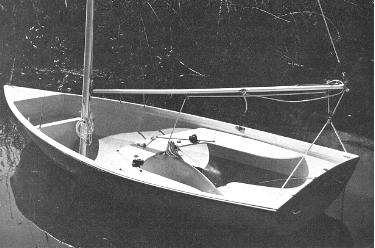 |
| FIG. 5-1-This neatly rigged boat is
ready to receive the sails. The running rigging is
clearly shown. This mainsheet rig is like that shown by
Fig. 5-4. The clew outhaul slides on a track with a line
securing it to a jam cleat on the side of the boom. The
aluminum tubing boom is held in position by the main
halyard. The main and jib halyards are neatly coiled in
position on the mast. Note the tracks with sliding cam
cleats on each side of the centerboard for controlling
the jib sheets. |
INTRODUCTION
The
RUNNING RIGGING consists of the lines used for hoisting and
controlling the sails directly, or indirectly such as through
control of the boom. The boat in Fig. 5-1 shows many of the lines
used for the running rigging in position. The running rigging
moves about the boat, or can be moved. The LINES are usually made
from ROPE. Once the rope becomes operational in the boat, it is
then referred to as a “line”. This then is the
difference between line and rope. Most lines on small sailboats
are made from synthetic twisted or braided rope, such as
polyester or polypropylene. Nylon is usually not a good line
because it stretches too much. Ropes of natural materials such as
hemp are seldom used anymore. Wire rope is sometimes used for
some running rigging, but must be connected to rope at the moving
ends that must be handled. A type of rope made especially to be
easy on the hands is called “YACHT BRAID” or other
similar proprietary name, and is more costly than the normal
braided line. Rope sizes are commonly noted by the approximate
diameter of the rope, even though it was once common to give the
size by the circumference.
HALYARDS
The
lines used for hoisting and lowering the sails are called
HALYARDS. The halyards run up and down the mast across a sheave
(pronounced “shiv”) at or near the top of the mast.
Halyards that are outside the mast are called
“external” halyards, and those that run inside a hollow
mast are called “internal” halyards. Halyards on small
boats can be made of rope, and often stainless steel wire rope is
also used. When wire rope is used, it should be the flexible type
such as 7 x 19. In the case of wire rope halyards, a portion of
braided or twisted rope must be attached to the running end so
the crew can handle the halyard without injuring their hands. The
braided rope is then attached to the wire rope either with a
Nicopress eye, or by a special splicing. On large boats, special
halyard winches designed for wire rope preclude the need for a
rope tailing.
Several
methods are used to attach the halyards to the head cringle of
the sails. Probably the most common method is the use of a
SHACKLE, a “U”-shaped fitting with an openable pin at
the open portion of the “U” which passes through the
head cringle (see Fig. 6-2). The
halyard is attached to the shackle either with a spliced eye,
Nicopress eye, or it is sometimes merely tied by a knot. A better
method when wire rope is used is to use a ball joint with the
shackle fitted onto the wire rope halyard before the ball has
been swaged on (see Fig. 4-2
‘a’). When wire rope halyards are used with a ball
joint, a HALYARD HOOK should be used near the masthead. This
fitting prevents hoisting the sail beyond a predetermined point
up the mast. Sometimes an additional halyard hook is located near
the mast base for the running end of the wire rope halyard with
another ball swaged at this end to secure the halyard.
| Another method used to attach halyards to
sails is with BRUMMEL HOOKS (as shown in Fig. 5-2). These
are special patented fittings used in pairs which allow
quick attachment once you get the hang of using them. The
Brummel hooks come in a wide variety of sizes and types
which can be used for other situations as well as with
halyards. One hook passes through the cringle at the head
of the sail, and another goes through the eye at the end
of the halyard, or can be merely knotted to the halyard.
The two connect with a twist of the wrist. |

FIG. 5-2-Brummel hooks are patented
fittings used in pairs. They are used to secure lines
together or lines to other items such as sails. A twist
of the two hooks is all that is required to join or
release them. |
SHEETS
The
lines used to control the trim or position of the sails are
called SHEETS. The line used to control the mainsail is called
the MAINSHEET, and the line used to control the jib is called the
JIB SHEET. Rope is used for the sheets, and “yacht
braid” type is often used because it is easier on the hands
and does not kink or jam as easily as twisted rope. Because the
force of the wind on the sails is often greater than the strength
of the crew, it is often necessary for the sheets to have a
built-in “mechanical advantage.” This is where the
various blocks (or “pulleys”) and winches come onto the
scene in various configurations to ease the work of the crew.
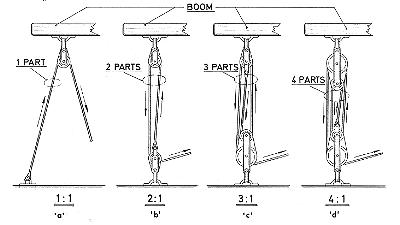 |
| FIG. 5-3 - Various tackle
configurations. The power of a tackle depends on the
number of "parts" in the tackle. Actually, 'a'
is not really a tackle as the block merely changes the
direction of the line, thereby affording no gain in
power. Fiddle blocks are shown for clarity where two
sheaves are used, though double blocks, with side by side
sheaves, would give the same result. The arrows show the
direction the line will move when pulled. |
When the sheets are lead
through a system of blocks, a TACKLE is formed that,
depending on the number of “parts,” will
decrease the effort required to do the work. This is
called “mechanical advantage” and is shown by
Fig. 5-3. All main sheet configurations are nothing more
than variations on these basic tackles, even though the
location of the various blocks may disguise the number of
parts used in the tackle. In figuring a tackle, it is
usual to deduct 10% from each “part” per block
to allow for the friction caused at the sheave in the
block. Also note that the more parts in a tackle, the
more line you must have and consequently the more line
you will have to pull through the tackle to move the
object a comparable distance.
Sheet rig types come in an infinite
variety of configurations, and some of the more common
main and jib sheet rigs have been shown in Figs. 5-4
through 5-13. To run the sheet through the blocks is to
REEVE the sheet, and it is a good practice to knot the
running end of all sheets so they will not inadvertently
pass through and out the blocks, causing loss of control
of the sails.
Note that in many cases the mainsheet
forms, or is used in conjunction with, the TRAVELER. The
traveler lets the mainsheet rig or unit move or
“travel” from one side of the boat to the
other. Travelers can range from the combination
mainsheet/ traveler type, or a simple length of line, or
very elaborate fittings complete with tracks using blocks
with ball or roller bearings and lines to control them.
|

FIG. 5-4 - Ratio 2:1. A simple
mainsheet set-up which uses a rope or wire rope traveler.
Although the traveler is shown deadending to eye straps,
one end could be made adjustable by belaying to a jam
cleat. The mainsheet can be held by hand or a block or
cam cleat can be used as shown in Fig. 5-5. 
FIG. 5-5 - Ratio 3:1. The mainsheet is
used as the traveler in this rig.
|

FIG. 5-6 - Ratio 2:1. This mainsheet is
also used as the traveler, but requires at least some aft
deck area. The main feature of this layout is the minimum
of hardware required. Because the sheeting lead on the
boom is at the aft end, roller reefing can easily be
incorporated by hanging the side shackle block from a
swiveling tang on the end of the boom. |

FIG. 5-7 - Ratio 4:1. This mainsheet
rig is handy to use where roller reefing is desired. It
would be possible to mount the lower fiddle block to a
track so it could to move each side with the boom, acting
as a traveler. If roller reefing is not used, the
mainsheet arrangement could be located at some location
along the boom, although this would increase the effort
required to move the boom. |

FIG. 5-8 - A system similar to Fig.
5-7, but using a rope or wire traveler similar to Fig.
5-4. This arrangement could also be located at the end of
the boom for use with roller reefing. A cam cleat could
be used at the swivel block so that the line need not be
hand held. |
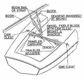
FIG. 5-9 - A rather elaborate system in
that the traveler can be adjusted with lines each side
via cam cleats. The fiddle block with cam cleat is used
so that the line need not be hand held. |
| Winches ease the work
required in pulling or trimming the sheets, such as on
jib sheets, as in Fig. 5-13. A winch gains mechanical
advantage due to its gear ratio, diameter of the handle,
and by the drum diameter of the winch. To determine the
mechanical advantage (or power ratio), use the following
formula: Radius of handle divided by the Radius of the
drum X the Gear ratio = Power ratio. This means that
power can be gained by either increasing the gear ratio,
or radius of the handle, or decreasing the drum radius,
or a combination of all three. Usually the drum radius
should not be decreased because the winch will then do
the work more slowly. On small boats such as being
discussed here, most winches will not have gears and are
thus referred to as “direct drive” winches such
as shown in Fig. 5-14. Often used on small boats are
winches which do not have handles either, and these are
called “snubbing” winches (Fig. 5-15). Winches
are usually relatively expensive items, and because
mechanical advantage can be gained by other means, they
are considered “deluxe” equipment on boats
under about 25' in length. |

FIG. 5-14 - This is a typical example
of a ratchet winch, which uses a
handle, for controlling jib sheets. |

FIG. 5-15 - A typical snubbing winch
as used for jib sheets on
small sailboats. No handle is used. |
| FIGS. 5-10 through 5-13
show various jib sheet configurations. Jib sheets are
usually two part lines secured at the mid length to the
jib clew cringle usually via a shackle. This means that
the hardware to control one side of the jib sheet will be
duplicated for the other side; in other words, each side
of the boat will have the fittings shown. |

FIG. 5-10-A fairlead on a slide allows
adjustment of the jib sheet lead point via the track. The
sheet can be hand held or belayed to a cleat at some
convenient point. |

FIG. 5-11-Similar to the foregoing but
the line is belayed with a cam cleat mounted directly on
a slide which runs on the track. |

FIG. 5-12 - This system provides a
power advantage of 2 to I (before allowing for fiction)
to the jib sheet. The pad eye is mounted outboard of the
track and two bullet blocks are shackled to the sail (one
for each sheet for each side of the boat). The line then
passes through a fairlead slide on a track and then aft
to a jam or cam cleat. Optionally, the cam cleat could be
mounted on the slide as for Fig. 5-11. |

FIG. 5-13 - This jib sheeting method
gains power through the use of a winch. The power of such
a rig is directly dependent on the power of the winch
that can be varied to suit. A fairlead on a slide could
be used on the track, however, the swivel block reduces
friction and chafe. A snubbing winch is shown in this
example, although a winch with a handle can be used. The
line must be belayed to a cleat beyond the winch. Note
that the lead from the swivel block to the winch is
fairly horizontal, as it should be. |
JIB SHEET LEAD
The sheet used to control the jib must be
lead to a point on the boat that affords optimum setting
of the jib (if one is used). If a Genoa jib is used, a
separate sheet lead must be determined for this sail
also. Since the jib sheets are in two parts (one for
starboard, and the other for port), a lead point will be
located on each side of the boat. In determining the lead
points, the designer probably uses a formula similar to
that shown in Fig. 5-16, which is at best always an
approximation. Because methods used to determine jib
sheet leads are approximations, and because no two sails
will trim the same, it is best to make the sheet lead
point adjustable by using lengths of tracks and sliding
fittings attached to them. Another method for determining
the jib sheet lead, at least on small boats, is to
actually sail the boat with the jib in position and
thereby determine the optimum setting in actual use. When
the optimum point has been located, mark with a pencil
and attach the appropriate fittings to the deck.
|

FIG. 5-16 - A common method used for
locating the jib and Genoa sheet leads is graphically
shown. The results are usually acceptable, but it is wise
to use tracks so minor variations in sheet lead can be
made. |
DOWNHAULS AND BOOM VANGS
Not all boats use downhauls or boom
vangs, but they are used enough to warrant discussion. A
DOWNHAUL is merely a line used to haul down on something,
usually the tack of the sail, or the boom where the tack
of the sail is located (see Fig.
3-12). A boom downhaul fitting or eye is often a part
of the sliding gooseneck, to which the downhaul is
attached to prevent the gooseneck from sliding up the
mast. Once the sail has been hoisted with the halyard and
pulled taut to a cleat, the downhaul can be used to gain
further tension along the luff of the sail by pulling
down and making fast to a cleat. Naturally, a similar
downhaul could be used on the jib. A special type of
downhaul called a “CUNNINGHAM” requires that
the sail have an additional cringle usually located
several inches above the tack cringle. The
“Cunningham” is usually used on competition
boats where more shape control of the sail is desired
along the luff, but because of the racing rules, the boom
cannot be hauled down below a certain pre-designated
point.
A BOOM VANG (also called a “go
faster” and “kicking strap”) is a device
that performs several functions. The boom vang is a
tackle arrangement (see Figs. 5-17 and 5-18) connected at
one end to the mast near its base, and with the other end
preferably about 1/3 the distance of the boom aft of the
mast. The boom vang helps take the undesirable
“twist” out of the sail on all courses off (or
away) from the wind, flattens the mainsail on a tack
(sailing in the direction of the wind), and prevents the
boom from lifting in case of accidental jibes (the boom
moving rapidly from one side to the other when sailing
downwind). |
 |

|
| FIG. 5-17 & 5-18 -
Two boom vang tackles with fittings. The upper block is
attached to the boom, while the lower block is fastened
to the mast base or near the mast base on deck. These
boom vang tackles could also be used for mainsheet rigs
if desired. Fig. 5-17 (left) has a power ratio of 3 to 1.
Fig. 5-18 (right) has a power ratio of 4 to 1. |
HOW TO FIGURE A TACKLE
In order to figure a tackle to control a
mainsail, for example, you must first know the area of
the sail. Once the area of the sail is known, figure the
“load” caused by the wind on the sail. In
figuring for a mainsail which has the mainsheet lead at
the end of the boom, figure wind load by multiplying the
sail area by 1.5 lbs. per square foot. If the mainsheet
leads to the boom midpoint, multiply the sail area by 3
lbs. per square foot. (For figuring the jib or Genoa,
also multiply by 3 lbs.) Actually, these factors are only
estimates by rule-of thumb and allow a safety factor in
consideration of varying sailing conditions, rig designs,
and wind forces up to 20 knots, but the results will
usually be close enough.
If, for example, a mainsail has 100
square feet of area, the mainsheet load at the end of the
boom would be 100 square feet multiplied by 1.5 lbs. and
would equal 150 lbs. Obviously, in order to control this
sail it would require 150 lbs. of “pull” at
times on the sheet. So to reduce this effort, we devise a
tackle. But how many “parts” should be included
in the tackle? Again a rule-of-thumb is used which says
that most people can pull 30 to 50 lbs. on a line BY
HAND. If using a cam cleat on the end of a line, this
figure can be increased, say up to 75 lbs. or more for
he-man types! But, in most cases, it is good to stick to
the 30 to 50 lb. range, if practical.
The ability of a tackle to do work
depends on the number of “parts” or lengths of
line BETWEEN the blocks as shown in Fig. 5-3. The more
parts, the easier will be the job, but consequently the
longer will be the length of line AND TIME to move the
load or boom a given distance. To determine the effort
required on the line when rigged in the tackle, divide
the total wind load by the number of parts in the tackle.
For example, using our 100 square foot sail, divide the
wind load of 150 lbs. by 4 (if we wanted a 4-part tackle)
and arrive at 37.5 lbs. of pull required to move the boom
or load. However suitable this figure may be, we must
DEDUCT a certain amount that will be lost due to friction
caused by the sheaves in the blocks, and other factors
that take away from our gain in mechanical advantage.
Again another rule-of-thumb is used which figures a 10%
loss for every sheave used in the tackle. Therefore, with
a 4-part tackle which has four sheaves, multiply each
sheave by 10% for a total of 40%, which is then
multiplied against the total wind load (40% x 150 lbs.)
for a total of 60 lbs. lost to friction and other losses.
(While the 10% figure is not technically exact, it is
close enough to use as a practical short cut, and it does
yield conservative results.) To the result (60 lbs.) add
150 lbs. (wind load) for a total load of 210 lbs. Divide
this figure by the number of parts in the tackle (4) for
a result of 52.5 lbs., or just about the maximum for
holding a sheet by hand in a 20 knot wind. If we use a
jam cleat to secure the sheet, this tackle will prove
sufficient to do the job under just about all conditions
short of having to reduce sail area. This example can be
used to figure other tackles as well. In summary:
SAIL AREA X FACTOR (1.5 OR 3) divided by NUMBER OF PARTS
IN TACKLE EFFORT (BEFORE FRICTION LOSS). To figure
power loss in tackle:
WIND LOAD X 10% PER SHEAVE FRICTION LOSS; WIND LOAD +
FRICTION LOSS = TOTAL LOAD IN LBS.
To figure load on end of sheet which crew must handle:
TOTAL LOAD IN LBS. divided by NUMBER OF PARTS IN TACKLE =
LOAD IN LBS. AT END OF SHEET.
|
Chapter 6
.....deck
fittings
INTRODUCTION
"Deck
fittings” is a general classification for all hardware used
with the running or standing rigging, as well as the spars, even
though the fittings may not always be mounted to the deck. Deck
fittings may be located on cabin tops, cockpit members, and
centerboard trunks as well. There are endless numbers and styles
of fittings available, and the number of new fittings and
inventions, plus modifications to existing ones, is constantly
increasing. We will attempt to describe those which are most
generally used in the size sailboats under discussion.
BLOCKS
A
BLOCK is a wood, metal, or synthetic casing that contains one or
more grooved pulleys called sheaves. Blocks are the primary
pieces of equipment in the running rigging, and come in a wide
variety of sizes and types. Besides adding mechanical advantage
to the running rigging, blocks are used to change direction of
the line passing through them. Conventional blocks must be
attached to something in order to work, and the most common
method used is by a shackle that is usually an integral part of
the block. Three types of shackles are used; front, side, and
swivel shackles. Fig. 6-1 shows the difference between front and
side shackles, but the trend is to fit blocks with adjustable
shackles which can be mounted either with a front or a side
shackle using just one block or with a swivel shackle. A front or
side shackle is used to keep the block in one position or plane
of reference, whereas a swivel shackle allows the block to turn
to any position.
 |
 |
| FIG. 6-1 - The anatomy
of blocks. Not all blocks have all of the above parts.
Some blocks have shackles that swivel or are adjustable
to either side or front shackle locations. A block with
one sheave is a single block; with two sheaves a double
block; etc. |

FIG. 6-2 - This drawing shows hardware
items and how they function on the boat. Note that all
lines used to control various functions of the rig lead
to a point convenient to the helmsman. |
A BECKET is often fitted to
blocks at the opposite end of the shackle. The becket is a
fitting on the block onto which a line with an eye, or another
fitting such as a hook, can be attached, as in forming a tackle.
Some of the common blocks are illustrated in Fig. 6-2.
A
FIDDLE BLOCK as shown in Fig. 6-3 contains two sheaves, one above
the other with one usually smaller in diameter than the other. It
looks like a “fiddle.” A fiddle block may have a becket
as well as a cam cleat arrangement (see Fig. 6-4) for use with
main sheets and boom vangs. A CHEEK BLOCK (see Fig. 6-2) lays
flat to its base, with the base being fastened to the deck. The
cheek block is commonly used to change direction of a line.
SWIVEL DECK BLOCKS (Fig. 6-5) have a base which fastens to the
deck and allows the block to assume a near-vertical position
capable of swiveling in any direction. A BULLET BLOCK is a single
block of small size which usually has no shackle (see Fig. 5-12).
The top of the bullet block is usually shaped to attach through
the eye of a line, an eye strap, or to a boom bail. A TRAVELER
BLOCK is one with two sheaves, one above the other, and with one
at right angles to the other (see Fig. 6-2). One sheave is for
the traveler, and the other for the mainsheet. No shackle is
used. Sometimes two bullet blocks interlocked at the straps can
be made to form a traveler block.
When
wire rope is used, blocks must be used which are intended for
this material. Some blocks are available which have sheaves
suitable for use with both rope and wire rope. The sheaves of
these blocks have a regular groove for the rope, and a narrower
but deeper groove within the regular groove to suit the wire
rope.

FIG. 6-3 - A typical example of a
fiddle block. |

FIG. 6-4 - A fiddle block with a
built-in cam cleat which can be used with various
mainsheet and boom vang rigs. |

FIG. 6-5 - A swivel deck block allows
the sheave to turn to the proper direction for the line
leading through it. |

FIG. 6-6 - The cams of the cam cleat
hold the line but it can be quickly released with a flick
of the wrist. |

FIG. 6-7 - This is the deluxe mainsheet
cam cleat which swivels, allows a fairlead to the main
sheet and belays the line so it does not have to be hand
held.
photo courtesy Schaefer Marine Products |

FIG. 6-8 - A swiveling mainsheet cam
cleat mounted on a bracket on the daggerboard trunk. The
mainsheet passes through the into the cam cleat. The
looped wire (right) prevents the line from jumping out of
the cleat when released. Note the pin on the daggerboard
trunk to “lock “ the daggerboard in position. |
CAM CLEATS
A
CAM CLEAT is a fitting used to belay (halt and secure) a line.
The line passes between two serrated cams which allow the line to
be pulled through in only one direction. To release the line, it
is pulled up and out of the cams. Fig. 6-6 shows a typical cam
cleat. Cam cleats often have a fairlead to guide the line into
the cams. Regular cam cleats are normally mounted flat to the
deck. A cam cleat arrangement is often attached integrally to a
fiddle block for adjusting a boom vang or main sheet. A deluxe
fitting is a swiveling mainsheet cam cleat (Figs. 6-7 and 6-8)
which comes with a block and a fairlead to change direction of
the mainsheet, leading it into the cam cleat. The benefit of this
fitting is that the helmsman need not hold onto the mainsheet,
but it can he released in an instant by giving it a yank upwards.
It also swivels so the sheet will be at hand on any tack.

FIG. 6-9 - A selection of tracks and
slides. Some are of stamped metal while others are
extruded; aluminum, stainless steel, and plastics are
common materials used. The slides shown are designed to
fit the tracks. |
TRACKS
TRACKS
are formed metal or plastic rails on which fittings can be
attached to allow them to move. A piece of track is used where it
is desirable to have the position of the fitting adjustable.
Tracks can also be used to attach the sail to the spars in some
cases. Tracks are commonly used for the jib and Genoa sheet leads
which pass through fittings attached to slides moving on the
tracks. These fittings can range from a fairlead slide, or a
block on a slide, or even a cam cleat on a slide. Some typical
slides and tracks are shown in Fig. 6-9. Tracks are also used for
the clew outhaul slide and for sliding goosenecks. When the
gooseneck mounts to a slide, a downhaul is used as well to allow
for adjustment. Jib and Genoa tracks, and tracks used for
travelers should be fitted with stops at the ends to prevent the
fittings from sliding off the tracks. In selecting tracks,
remember that the fitting to be used must be made to fit the type
track being used.
CLEATS, FAIRLEADS, AND EYES
CLEATS
(Fig. 3-19) are fittings to which
lines are belayed and secured. With small sailboats, a common
cleat is a JAM CLEAT. These allow a line to be taken through or
turned around the jam cleat in such a manner so that it will not
slip free. Jam cleats are commonly used to secure halyards and
sheets. Many kinds of patented-type jam mechanisms are also
available which are often referred to as “jam cleats”
because they perform the same function. FAIRLEADS are actually
any fittings which give a “fair lead” to any line (see
Fig. 6-2). Fairleads are usually eye-shaped fittings which
minimize or prevent chafing of the line which passes through it.
Fair fairlead (left) and leads usually change the direction of
the line passing through them as well. As noted previously, a
block can be used to change the direction of a line also, thereby
making it a type of “fairlead” too. Fairleads can be
fixed to the deck, swiveling, or mounted on tracks.
EYES
such as PAD EYES, DEAD EYES, and EYE STRAPS are used to secure a
line or a fitting to the boat (see Fig. 6-2). Many types are
available to fulfill a variety of functions. Pad eyes, when
fitted with a shackle, can secure a block to the hull and allow
it to adopt the right position for proper sheet lead. Deadeye
straps are often used to secure a traveler line or mainsheet to
the hull. The traveler or mainsheet is knotted to prevent it from
coming through the eyes. \
WINCHES
Some
comments on winches have been made previously. The variety and
type of winches available to the sailor is enormous, but for the
small boat sailor, winches usually are restricted to the smaller
sizes used to control the jib and Genoa sheets. Winches can be
used for the halyards, boom vang, and mainsheets, if desired. On
small boats the cost is usually prohibitive, and the extra power
gained is not required, as these lines can be handled by the crew
or by other means, such as tackles, equally well.

|
FIG. 6-10 - The rudder is connected
to the boat with gudgeons (the fittings on the boat) and
pintles (the pin fittings on the rudder). They allow the
rudder to swing freely in order to steer the boat |
RUDDER FITTINGS
Small
sailboats usually have rudders which are called
“outboard” rudders because they hang onto the aft end
of the boat in full view. Boats which have rudders under the hull
and the rudder stock passing through the hull bottom are said to
have “inboard” rudders, but these are usually
associated with large boats. The ordinary small boat rudder is
attached to the boat with fittings that also allow the rudder to
pivot or turn. These fittings are called GUDGEONS and PINTLES.
These are arranged in pairs, with the gudgeons usually being
attached to the boat, and the pintles fastened to the rudder. The
pintles are strap-like fittings with the rudder fitting between
the straps, and with a pin at the forward edge which fits into
the “eye” of the gudgeons (see Fig. 6-10). As with most
fittings, many sizes and types are available. Often gudgeons and
pintles come in pairs which have a long pintle and a shorter one.
These types make it easier to put the rudder on the boat, as the
long pintle will be in position first, thereby acting as a guide
for the short one. If both pintles are the same length, both must
fit into the gudgeons at the same moment, which is frustrating at
times, especially when trying to place the rudder in position
when afloat. Because many small boat rudders are made of wood,
the tendency is for these to float up and out of the gudgeons, of
course, making for an immediate loss of steering and much
embarrassment. A device called a RUDDER STOP can be used to
prevent this from occuring. These are standard marine hardware
items very simple in nature.
 |
 |
| FIG. 6-11 - This
special factory-made kick-up rudder fitting incorporates
the rudder gudgeons and pintles. The fitting mounts to
the transom of the boat but allows the rudder to be
removed. This fitting is normally used on small boats
only. |
For small sailboats which land on
the beach, it is desirable to have the rudder “kick up”
when approaching shallow waters. Special “kick-up”
rudder fittings such as shown in Fig. 6-11 are available, which
also have the gudgeons and pintles attached as an integral unit,
and perform this function. With a little effort, you can make
your own “kick-up” rudder similar to the detail shown
in Fig. 6-12.

FIG. 6-12 - One method of making a
kick-up rudder using wood. When the pin is removed, the
rudder will automatically come up when hitting the beach. |
 FIG. 6-13
- This tiller extension was made by merely cutting the
tiller in half at the forward end and fastening it with a
bolt. A more convenient type uses a swivel connection in
lieu of the bolt for universal action. The line shown is
a rope traveler which can be adjusted in length and is
secured to the jam cleat on the deck.
|
The rudder is controlled by a handle
called the TILLER. Sometimes the tiller passes through a
hole in the transom (back of the boat), but usually it is
located above the aft deck area and pivots up and down so
the crew can move about easily. The length of the tiller
is best determined in actual use, so it should be made
longer than necessary. It’s much easier to cut off a
long tiller than to add length to a short one. A device
recommended for easier control, especially when tacking
or sailing to windward, is a TILLER EXTENSION or
“hiking stick,” an example of which is shown in
Fig. 6-13. When sailing to windward in a small boat, the
boat usually heels considerably and the crew must lean
out to windward (or “hike out”) to counteract
this. In order to hang onto the tiller in this position,
an extension is required, fixed to the forward end of the
tiller and preferably fitted with a universal-type joint.
Naturally, the length of such a unit is best determined
in actual use, so it is best to get a long one which can
be cut, instead of getting one too short which can’t
be added to. |
Chapter 7
.....installing
fittings to the hull
GENERAL PRINCIPLES
Fittings
for the running and standing rigging must be capable of resisting
considerable strains. Therefore, it is always recommended that
fittings be through bolted whenever possible, with the fitting
being backed up with oversized solid blocking, especially on the
underside of thin fiberglass or plywood surfaces such as decks.
Use large flat washers under nuts, and bedding compound under the
fittings to prevent leaks. Where it is not possible to use
through bolts, then long screws of the largest possible shank
diameter should be used, driven into solid material below. These
rules apply to fittings wherever they may be required, whether on
cabin tops, cockpit soles, decks, or centerboard trunks.
On
wood hulls, finding solid material or providing solid backing
blocks is usually a simple matter. On fiberglass hulls, backing
blocks may have already been fitted when the hull was fabricated,
or the hull may have been reinforced with extra laminate build-up
in the area where fittings are to be located. If this hasn’t
been done in one form or the other, the builder must provide the
solid backing material to receive the fastenings for the fitting.
The wood blocks can be secured in place with a resin saturated
piece of fiberglass cloth or mat.
Fastenings
in all cases are preferably a non-corrosive type, which usually
means stainless steel, bronze, or at least hot dipped galvanized.
Do NOT, however, use hot dipped galvanized fastenings with, for
instance, bronze fittings, as the two metals are dissimilar and
corrosion will dissipate the fastener (at least in salt water). A
good rule-of-thumb is to use the same type material in the
fastenings as is used in the fitting, except that stainless steel
can be used to fasten into aluminum.
INSTALLING CHAINPLATES
Chainplates
may be located on the outside of the hull, usually along the
gunwale or hull side rail. For a neater appearance, however, it
is more common to have them located inside the hull, projecting
through the deck or cabin top. When they are located inside, this
usually means that they must be mounted in position prior to the
completion of the hull, and especially before the decking is
applied (see Fig. 7-1). The position of the chainplates should be
determined by the designer or manufacturer of the boat. This
position will usually be in conjunction with a main strength
member such as the hull sides, structural bulkhead, or other
longitudinal framing member. As with other fittings, solid
backing blocks, or extra reinforcing of the hull on fiberglass
boats, should be provided for mounting the chainplates.

FIG. 7-1 - If building a boat and
through-deck chainplates are called for, they should be
installed and bolted in place before the deck is applied.
The photo shows the chainplates bolted in position on
each side, protruding far enough above the deck line to
receive the turnbuckle or other stay hardware. (Glen-L 10
is shown) |
Chainplates
can be made of any strong metal as long as it is non-corrosive.
However, it is common to purchase ready made chainplates which
are usually made from stainless steel strap with holes usually
drilled in each end. If in doubt about which size chainplate to
use, always pick one that is larger and as long as practicable.
Always bolt the chainplate in position with at least two bolts
per unit. Be sure to let the top end of the chainplate extend far
enough above the deck or cabin top to allow the shrouds to be
attached. Where chainplates protrude through the deck or cabin
top, the hole should be sealed in a water proof mastic. Special
covers are available which match the ready-made chainplates to
cover the hole and “dress up” the area where the
chainplates pass through.
If
in doubt about the location of the chainplates, remember that
they are located as far outboard as possible, as far as
strengthening the mast is concerned. They must not, however,
interfere with sail handling; especially when a jib is used.
Also, if a single shroud on each side is used, the chainplates
are usually located a little aft of the mast. When upper and
lower shrouds are used, the chainplate for the upper shroud is
usually directly to the side of the mast. The chainplates for the
lower shrouds are then located a slight distance forward or aft
of this chainplate. When more than one chainplate is required per
side, they should be separated by a distance of at least several
inches in order to transfer the strains to the hull.
INSTALLING DECK FITTINGS
Deck
fittings such as blocks, cleats, winches, tracks, and related
items should be installed with bolts or long screws as previously
noted. Fastenings are usually not provided with the deck fittings
when purchased because the lengths will vary from boat to boat.
In
installing fittings such as for the mainsheet, it is advisable to
mock-up the arrangement before fastening anything permanently in
position, especially if you are not familiar with the
configuration, or are figuring out your own arrangement. Tape the
fittings in position and check to see that all fittings are in
the proper position and plane of reference for smooth operation.
It would be mighty embarrassing to find that a cam cleat, for
example, was fastened in backwards! While the designer will
probably note the positions of the various fittings, the best
locations for the fittings can be determined. Also check the
position of the various jam cleats which will be used to belay
the various sheets and halyards. Obviously these jam cleats must
have a "fair lead" to the line and be in a position so
the line will stay secure. Always locate jam cleats so the pull
of the line is at right angles to the line of the fastenings; not
in line with them which will tend to pull the cleat out.
If
your rig has a jib, care must be taken in locating the jib sheet
lead points; the position where the lines controlling the trim of
the jib intersects with the hull. Designers use a formula for
determining these positions and it has been noted previously and
in Fig. 5-16. The builder can also use this formula, but because
conditions of use, the sails, and boats in general vary, the best
method for determining jib sheet leads is by actually sailing the
boat and pinpointing the lead position while using the jib.
Admittedly, this may seem tedious and inconvenient, but on the
smaller boats with jibs up to about 50 square feet, it is really
not too much effort.
With
either method, once the correct point is determined, a fixed or
adjustable lead fitting can be installed. On small boats, a fixed
lead need consist of nothing more than a fairlead fastened to the
deck on each side for each jib sheet. On larger boats, or where
more efficiency is desired, a track can be used on either side
with a sliding fairlead. This method allows for variable trimming
of the sheet when underway, which is desirable when the
conditions of sailing change. This track for the jib would be
located so the mid-length of the track is positioned at the point
found to be most efficient. The track used for the jib is usually
at least 12" long. On larger boats that use a Genoa, a
separate track is provided for this sail, each side of the boat.
The lead point for the Genoa can be found by the trial-and-error
method, but because of the size of the sail, this is difficult,
to say the least. For this reason, it is better to use the
formula provided to determine the lead point for the Genoa, and
then use a longer length of track for the fairlead slide so that
variations are possible. In most cases the Genoa track is located
fairly parallel along the sheer rail as far outboard as
practical. Track stops must be provided for all jib and Genoa
tracks at the ends so the slides will not come off when underway.
When
winches are required for handling sheets and halyards, their
position must be carefully determined. Halyard winches are
generally fastened to the mast, but are really not considered
necessary equipment on the size boats being considered here. This
leaves winches which are used for the jib or Genoa sheets. Here
again the position of the winches will usually be noted by the
designer, but as stated previously, this will be an
approximation, and the exact position for the winches is best
determined in use once the sheet lead points are known, or at
least mocked-up.
In
locating winches, several things must be considered. First, the
winch must be near at hand and convenient to use. If it has a
handle, clearance must be allowed for a full circle swing.
Winches may be located on deck, but it is common to raise them up
on blocking in order to clear cockpit coamings. If the winch is
blocked up, this blocking should be angled so the lead of the
sheet from the track is fairly horizontal to the winch. A cleat
is always used to secure the sheet after taking turns around the
winch. These cleats are preferably in a horizontal plane with the
winch as well.
When
installing “outboard” rudders on the transom, gudgeons
and pintles, as described in the previous chapter, are used.
Sometimes inboard rudders are used, and these are usually
detailed on the plans by the designer. With “outboard”
rudders, most commonly the pintles are bolted to the rudder. The
gudgeons are then screwed or bolted to the transom. Most boats
use a set of two each, and these should be spaced as far apart as
possible to distribute the strain on the rudder. Install a rudder
stop if there appears to be any tendency for the rudder to float
up and out of the gudgeons. Any number of types of rudder stops
are available, some of which may be integral with the rudder
fittings. Another method which can be used but is not very
seaman-like is to bend the pintles with pliers so they fit
tighter in the gudgeons.
 |
 |
 |
 |
| FIG. 7-2 through 7-5 -
Two types of mast steps are shown for use with aluminum
spars. The first pivots; the aft corner of the mast at
the base is radiused to allow clearance when pivoting.
The exploded view shows an internal stiffener used on
light masts to provide bearing for the bolt. The second
type of step is fixed to the deck and the mast sets onto
it. It is held in position by the stays. |
Installing
the mast step may not require any fittings if the mast is to be
stepped through the deck and provisions have been made in the
hull structure. However, with masts that are to be stepped on the
deck or cabin top, a means of securing the mast is required, and
this is usually by the mast step fitting such as shown by Figs.
7-2, 7-4, and 7-5. As noted previously, several types of steps
are available. Depending on the design, reinforcing below the
mast step may be required, such as a mast stanchion or large deck
beam. The reason for this extra support is that the mast is in
direct compression onto the boat and the considerable strain must
be transferred throughout as large an area of the structure as
possible. So it is important that the mast step be located
directly over these strength members and rigidly mounted. Mast
steps are preferably through bolted in any case.
Chapter 8
.....outfitting
spars
INSTALLING FITTINGS
As
noted previously, small boat spars are made of wood or aluminum.
Wood spars may be either solid or hollow, while aluminum spars
are hollow. Fittings on wood spars are usually screwed with wood
screws or through bolted. If through bolted, the bolts should
pass through solid wood blocking in hollow spars. Fittings on
aluminum spars can be bolted, but the number of through bolts in
an aluminum spar should be kept to a minimum, and the bolts
should never be tightened to a point that will collapse the spar.
Nuts on through bolts should be locked with lock washers or
self-locking nuts to prevent the nut from working free. Another
method to lock the nut is to cut off the end of the bolt just
above the nut and, with a center punch, drive the punch hard into
the center of the end of the bolt. This will spread out the metal
in the bolt and the nut as well, jamming them in position. Most
fittings on aluminum spars are secured with self-threading sheet
metal screws that should be of stainless steel. In fact, all
fastenings through the aluminum should be stainless steel to
prevent corrosion of the spar that can occur when dissimilar
metals are in contact in marine conditions. Lubricate sheet metal
screws with oil before driving. It is possible to use rivets to
fasten parts to the aluminum spars, especially with “pop
rivets” if you have the tool. These can be used on items
such as tracks or flat base fittings, but in any case the rivets
should be stainless steel or aluminum, and the hole of the rivet
filled with epoxy cement filler. If using aluminum pop rivets,
use plenty because they are not as strong as the stainless steel
type. Where plastic fittings are used, such as fairleads, these
can be secured with epoxy glue. When drilling for bolts in either
wood or aluminum, the hole should not be a sloppy fit, but should
be snug. Screw holes for wood screws must also be of the correct
size, and lead holes for the self-threading screws in aluminum
spars must be of the correct size required for the screw, which
is always less than the size of the screw.
 |
FIG. 8-1 - A Nylon fairlead, such
as used for the exit point of internal halyards, is
simple to install. Just drill a hole of the right size in
the mast and use a two-part epoxy adhesive to secure the
fitting in position. |
Where
internal halyards are required, it is best to lead wires through
the mast before outfitting so the halyards can be attached to
these for later reeving. On hollow wood masts, it is easiest to
do this before assembling the mast. The halyards, when run
internally, exit the mast near the base. The exit point must be
fitted with some type of fairlead. This may consist of merely a
hole with a plastic fairlead fitting such as shown in Fig. 8-1 to
prevent chafing the halyard, or can be the more elaborate coaming
pulley or sheave box arrangement. In any case, one exit is
required for each halyard, and it is convenient to locate the
exit for the mainsail halyard on the aft or port side of the
mast, and the jib halyard exit on the forward or starboard side
of the mast to avoid confusion. Some skippers use different
colored lines for halyards to keep them separated. If using wire
rope for the halyards, all sheaves must be for use with wire
rope, and a fairlead without a sheave should preferably not be
used. It is possible to bring the halyards through the mast base
where they can be concealed in the cabin, or in the forward cuddy
below decks space. This arrangement does have merits especially
with regard to clutter. One problem with the arrangement,
however, is that there is no good way of keeping water from
entering the hull through the holes required, which is especially
critical on cabin boats.
With
aluminum spars, most of the other fittings, such as the masthead
fitting, or boom gooseneck fittings are made up of aluminum
castings which fit the spar extrusion (see Figs. 8-2, 8-3, 8-4,
and 8-5). Once the lengths of the spars are known, these fittings
are inserted in position and screwed or riveted in place.
Aluminum spars are easily cut with a hacksaw if oversize, and
rough edges filed clean. When aluminum is used for the boom, it
is a simple matter to have roller reefing, as the roller reefing
gooseneck can be incorporated in the hollow extrusion. When using
aluminum castings for aluminum spars, it is often necessary to
file off rough edges. This is normal, and because of the relative
softness of the metal, takes little effort. Also, a little oil or
wax will make the fittings slip into the extrusion more easily.
Fittings on wood spars are fastened with wood screws or through
bolted. Goosenecks for wood booms usually have tang or strap-like
members into which the boom fits. These tangs can usually be
spread apart somewhat to suit the thickness of the boom. The
gooseneck is bolted through the boom as are boom bails where
required.
Masthead
fittings should be detailed by the designer of boats with wood
masts, and the larger the boat, the more elaborate the fitting.
On simple mastheads which have only one halyard, all that is
required is a sheave installed in a groove at the top of the
mast. A similar sheave may be used at the clew outhaul on the
boom. These sheaves use a pin axle driven through a hole, and the
ends are peened (flattened) over to keep it in position. Sheaves
are usually synthetic plastic material or metal where wire rope
is used.
BOLT ROPE GROOVES
On
spars which use a groove for the bolt rope of the sail, there
must be a means by which the bolt rope can enter the groove. On
wood spars, an area must be relieved using the method described
later, or by the directions in the plans provided with the boat,
if you are building your own boat. On aluminum spars which use a
groove, a portion of the mast must be filed away with a coarse
file (see Figs. 8-6 and 8-7). Do not cut away the groove
excessively, and make sure all rough edges are smooth to prevent
wear on the sail. A small fine file or rotary grinder plus emery
cloth will do the job. Look at the end of the mast to determine
the amount to remove. The length and position of the cutaway
areas should be provided by the designer of the boat, or by the
spar supplier. If the position or length required is not given,
it can be determined by using the sail as a guide. Hold the sail
so the top or head is 6" to 8" below the top of the
mast, and stretch the bolt rope tightly along the mast. Mark the
position where the tack of the sail falls along the mast, and
relieve an area 5" to 12" above the tack, both for
entry of the bolt rope and the gooseneck slide fitting. Remember
that the relieved portion must be above the gooseneck when the
gooseneck is positioned when pulled down by the downhaul (see Fig. 3-15).

8-6 |

8-7 |
| FIG. 8-6 & 8-7 -
Goosenecks used with grooved aluminum spars must be
relieved in order to fit the gooseneck into the groove.
Although a wood boom is shown, it could be of aluminum
also. The relieved portion is also required for the bolt
rope of the sail so the relieved area must be carefully
determined. When the boom is pulled down by the downhaul,
it cannot be in the relieved area; it must be below it as
shown by Fig.
3-15. |


